
THE ARCH PROJECT
THE ARCH PROJECT with an eye on solar and davits.
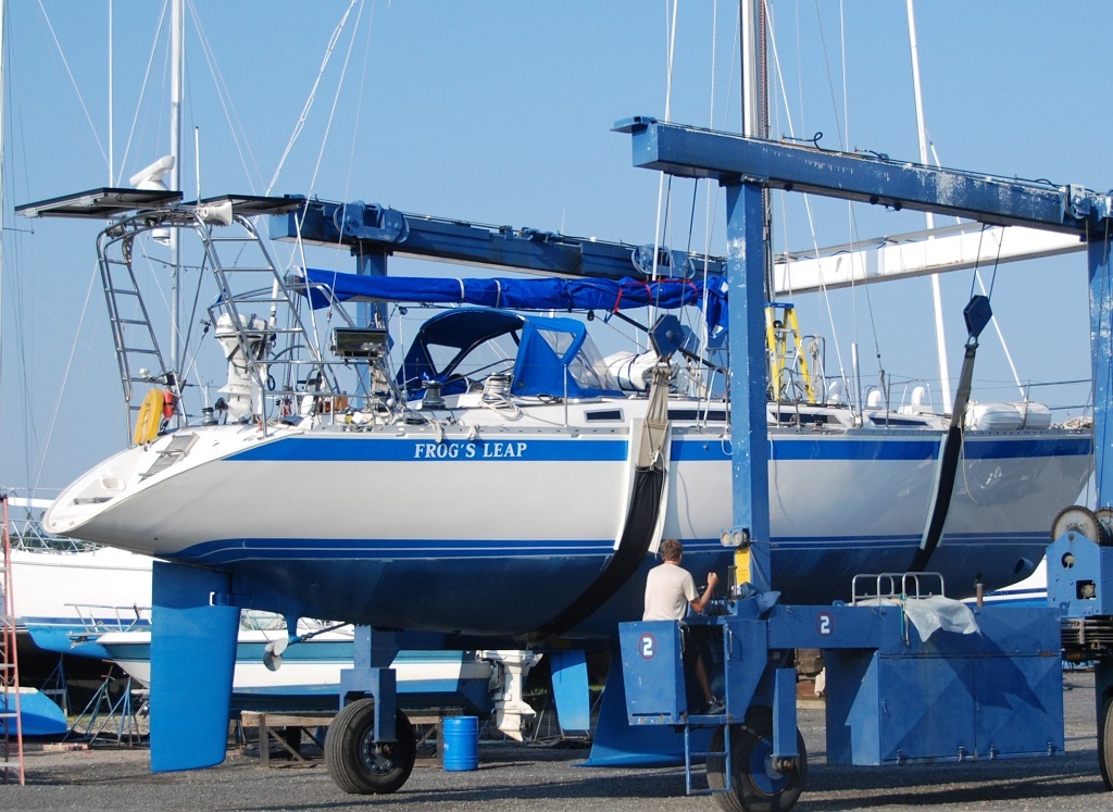
At the end of the first season in 2009, I came to realize that the radar post on the stern of the boat was poorly mounted. The base was made of mild steel welded onto the stainless tube and secured by rather small screws to the aluminum stern plate. The post was tied to the stern rail which served as the only support to keep it vertical.
Disliking the prospect of falling overboard while leaning on this post, and wanting for solar power, I started the design 2011, completing it in 2012.
Arches have multiple benefits, and the drawbacks are the usual nemesis of yacht design: Windage and weight. For a liveaboard cruiser, some expected performance loss is accepted, leaving room for reliability and assistance from systems in a short handed ecosystem. (As an example, (Luc Coquelin, a Route du Rhum racer, shared with us that he never uses water ballast when cruising, as the weight of food and other items on board helps keep the boat balance, even in a minimalist world.
My uses for power are typical of all sailors who live on board and make passages offshore. Watermmaking, autopilots, navigation, refrigeration and computers eat up most of the power budget, making solar an essential, thus an arch indeed is of benefit. While you can put solar panels on davits, and some hang them on lifeline-turned-liferails at the stern port and starboard, these solutions have more vulnerability in docking, and one still ends up with a stern mast for the radar and / or antennae.
As it is with most yachtie things, no standard exists and arches have to be custom designed. I had run into several skippers with good solutions from Wells Marina and other places, but the difficulty in 2010 was in accurately templatingthe work. Nothing beat at the time the proximity of the shop to the boat. Lockwood Boat works ( hyperlink) had two very capable fabricators at the time and the yard owner/manager agreed to a price which more or less matched the Wells Marine pricing.
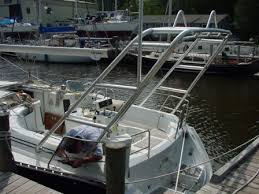 Ugly Arch
Design Challenge
It is difficult to design an arch that maintains the lines of the design intended by the naval architect. The goal of course is to avoid completely messing up the boat. This can happen if the arch feet are separated too far, or if the arch is too narrow and high on a narrow sterned boat, or if it looks like a tuna tower. All these traps can only be discovered by design, and 3D or photo overlays.
My design method was unconventional, in the absence of any drawings for the boat.
- Define the key constraints:
- Had to look right with the lines of the boat.
- Had to be capable of supporting two loarge or four smaller panels.
- Had to be retrofitted with davits eventually.
- Had to not look like a ladder leaning off the back of the boat.
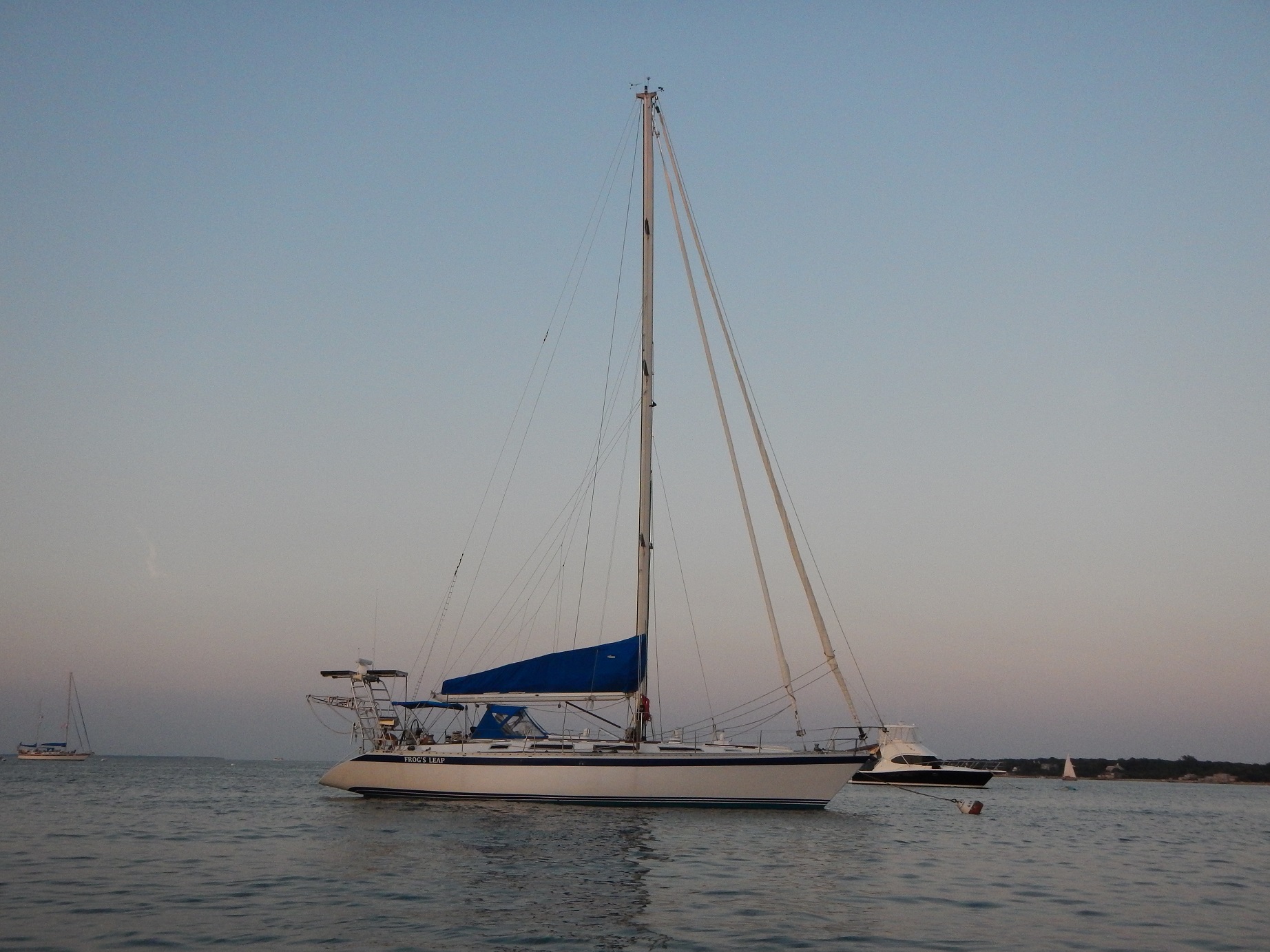
- Had to follow the projction of the sheerline up above the aft end.
- So the design process:
- Measure and build a wooden template to allow building a more rigidbase template. This was essential to ensure proper fit at the stern
- Build a two axis aluminum bracket template to allow to match the deck angles.
- Once completed, design could start.
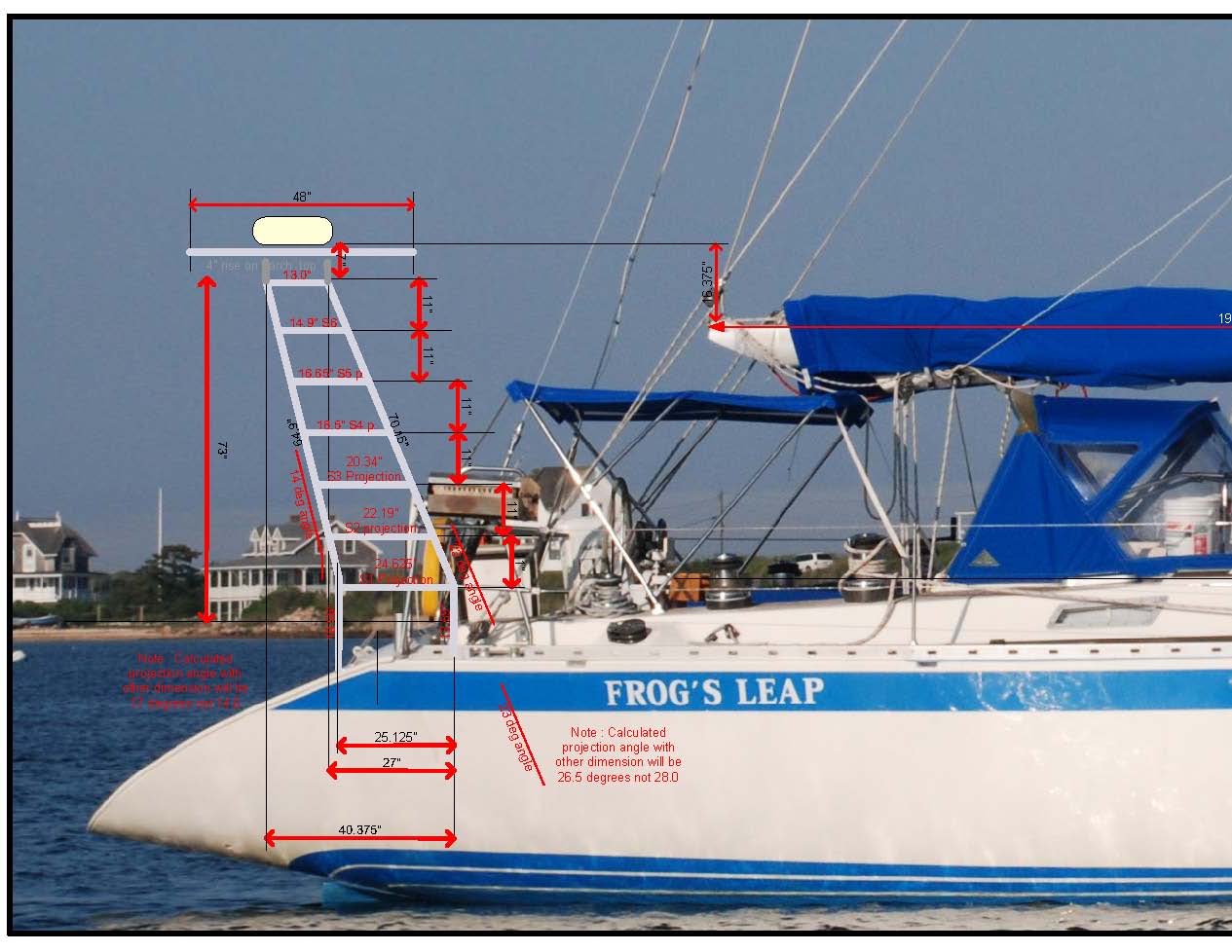
- Design the arch on three 3D projections of the boat, using properly scaled pictures pin a 2D drawing tool: Side view, top view, aft view.
- This was an iterative process with multiple passes to ensure the aesthetics were reasonably kind to the eye.
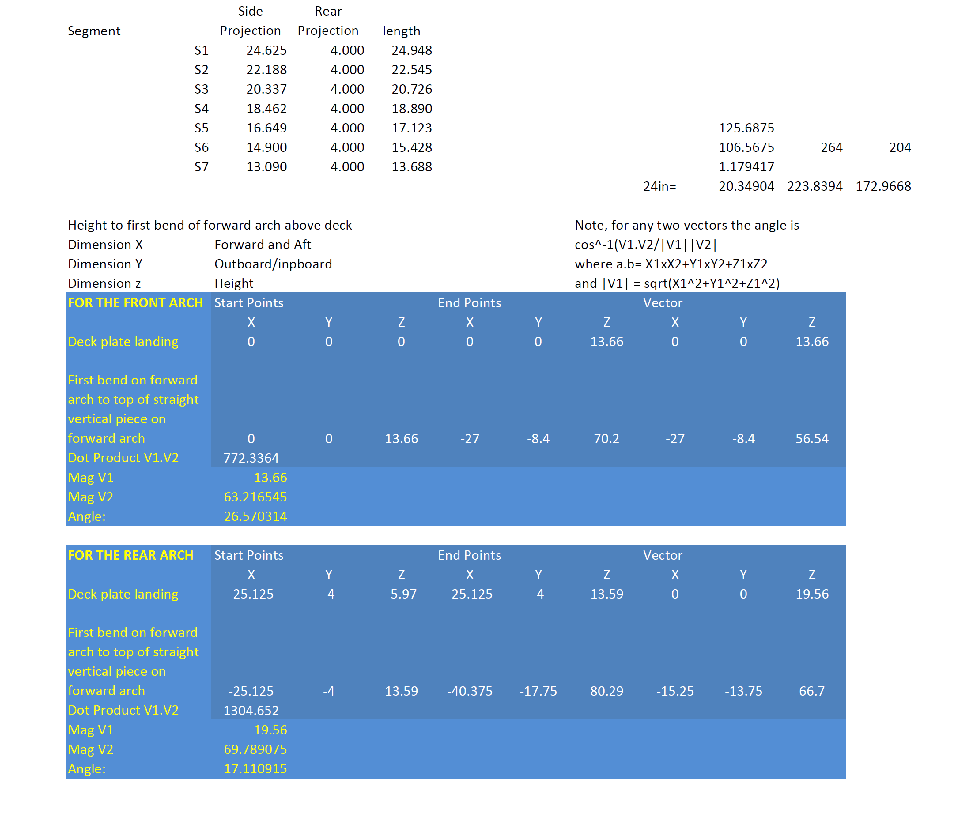
- Produce 2D drawings and calculate the exact length where compound angles were involved. The fabricators said my segment lengths were with a quarter inch or so from the actuals needed.
- Fabrication of two mandrel bends was done outside to allow a very tight turn at the front of the arch. This design feature was the key to managing the lines, because the arch leaves the deck at 90 degrees and turns to its angle aft after some height withing the pulpit height. This prevents the "ladder look"
- The other key measure is not to have the front arch section parallel to the aft section. They must meet at the top, within enough distance to mount things, but not be parallel, again to avoid this ladder look.
The arch fabrication was the job of the yard, as I did not weld at the time.This allowed time to reinforcing the transom with ½ inch G10 and several layers of glass matt and stitched engineered fabric. Epoxy of course is the best choice, for occupational health as well as structural strength, flexibility and fatigue performance reasons.
Holes were made in the deck, and an aramid-buta-n pressure gasket was used as a mounting base. These gaskets (trade mark is Blue-Gard) do conform, but because they are used in joints for steam high pressure lines they are quite strong under the compression forces of the pads against the deck.
 RIGGING
Boom T
For installation, the arch was raised to its position using a boom truck, and held in position. Three of us drilled holes in the boat, and the arch landing pads for the transom were tack welded to be fully welded in the shop. The final installation was a simple drop and bolt down through the deck. There was little time to pause and take pictures of the boom truck lift and bolt operation. With three people on the job and the equipment clock ticking, my extra pair of hands was needed.
Tidbits
- For gasketing the arch pad to the deck: Buta-N rubber sheets, available from McMaster Carr. This gasket material is used in high pressure steam plants, it is kevlar (Aramid) reinforced.
- A high quality polyurethane caulking ( ska 295UV, 3M 4200, TDS IS440)
- Use 316 machine screws fro a reputable supplier, not 304 type from the marine store. Grind the heads flat and polish them to a mirror finish.
- For weld passivation, use Spotless Stainless, which is citric acid, or make your own paste with fumed Silica and grocery stor purchsed citric acid
CREDITS
Such a project would not have been possible without help from many great friends. Thanks, Sebastien Granier Daisy Pelszynski Mike Vinik
Bill Lockwood, who runs one of the best yard in New Jersey, and his crew of brothers, sisters, and employees. Simply they are super multitalented machine operators, welders, fiberglass experts, machinists, storekeepers, and office workers. A great crew, and they will bend over backwards for loyal customers. Never once did they let me down.
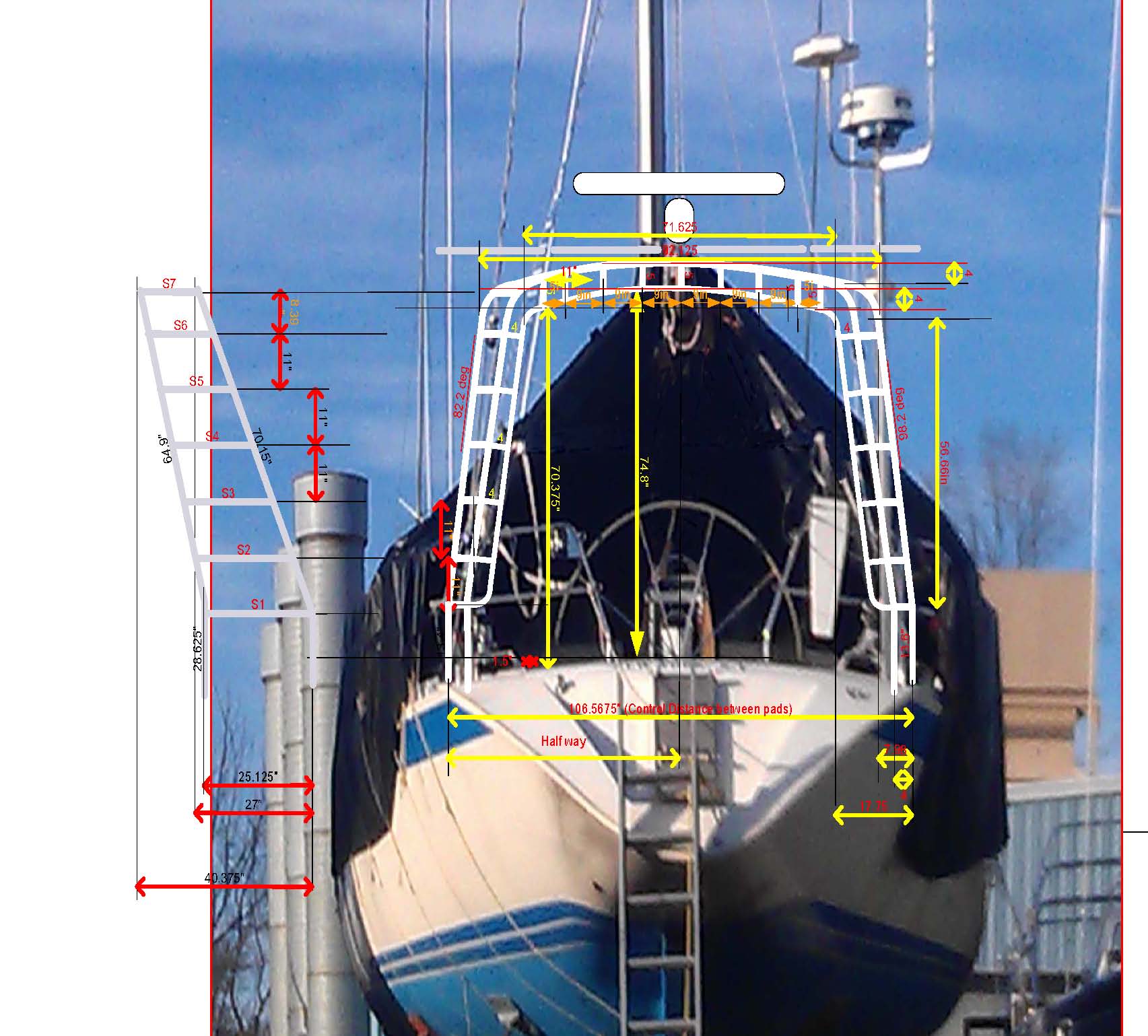
- The design approach for dimensioning the arch, based on a telephoto picture of the stern and overlays of dimensions after scaling the picture to the exact dimensions.
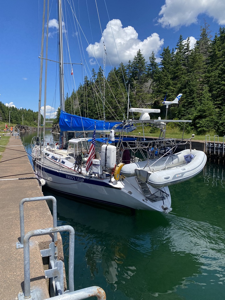
- The arch as built in the shop, on a base templatefrom actual remeasurement of the boat.
- The calculations of the arch segment lengths based on the two 2D drawings.
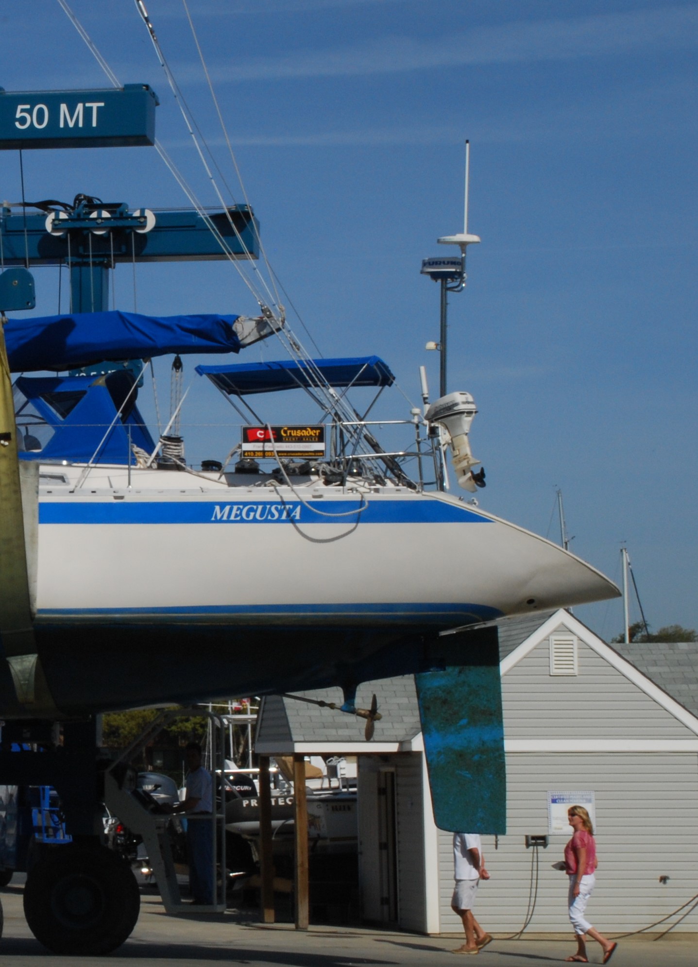
- The Before picture of the stern during the 2009 purchase survey of then-Megusta now Frog's Leap'